SuperNX / Tools / H7 tolerance chart
H7 Tolerance Chart
H7 hole tolerance by size
| Size over – to (mm) | IT7 (µm) | Upper ES (µm) | Lower EI (µm) |
|---|---|---|---|
| ≤ 3 | 10 | +10 | 0 |
| 3 – 6 | 12 | +12 | 0 |
| 6 – 10 | 15 | +15 | 0 |
| 10 – 18 | 18 | +18 | 0 |
| 18 – 30 | 21 | +21 | 0 |
| 30 – 50 | 25 | +25 | 0 |
| 50 – 80 | 30 | +30 | 0 |
| 80 – 120 | 35 | +35 | 0 |
| 120 – 180 | 40 | +40 | 0 |
| 180 – 250 | 46 | +46 | 0 |
| 250 – 315 | 52 | +52 | 0 |
| 315 – 400 | 57 | +57 | 0 |
| 400 – 500 | 63 | +63 | 0 |
A size belongs to the row where it is over the first value and up to and including the second (30 mm is in 18 – 30). Add the deviations to the nominal size for the limits: Ø25 H7 is 25.000 to 25.021 mm.
Quick question · anonymous, one click
Which CAD do you use?
What are you working on?
Thanks — that helps us decide which tools to build next.
Companion zones: H6, H8, h6, h7, g6, f7, k6, m6, n6, p6, r6, s6
Each cell reads upper / lower deviation in µm. The tables are generated from the same verified ISO 286 data as the fit calculator; r and s shafts change deviation inside the coarse size bands above 50 mm, so they get their own finer rows.
| Size over – to (mm) | H6 | H7 | H8 |
|---|---|---|---|
| ≤ 3 | +6 / 0 | +10 / 0 | +14 / 0 |
| 3 – 6 | +8 / 0 | +12 / 0 | +18 / 0 |
| 6 – 10 | +9 / 0 | +15 / 0 | +22 / 0 |
| 10 – 18 | +11 / 0 | +18 / 0 | +27 / 0 |
| 18 – 30 | +13 / 0 | +21 / 0 | +33 / 0 |
| 30 – 50 | +16 / 0 | +25 / 0 | +39 / 0 |
| 50 – 80 | +19 / 0 | +30 / 0 | +46 / 0 |
| 80 – 120 | +22 / 0 | +35 / 0 | +54 / 0 |
| 120 – 180 | +25 / 0 | +40 / 0 | +63 / 0 |
| 180 – 250 | +29 / 0 | +46 / 0 | +72 / 0 |
| 250 – 315 | +32 / 0 | +52 / 0 | +81 / 0 |
| 315 – 400 | +36 / 0 | +57 / 0 | +89 / 0 |
| 400 – 500 | +40 / 0 | +63 / 0 | +97 / 0 |
| Size over – to (mm) | h6 | h7 | g6 | f7 |
|---|---|---|---|---|
| ≤ 3 | 0 / −6 | 0 / −10 | −2 / −8 | −6 / −16 |
| 3 – 6 | 0 / −8 | 0 / −12 | −4 / −12 | −10 / −22 |
| 6 – 10 | 0 / −9 | 0 / −15 | −5 / −14 | −13 / −28 |
| 10 – 18 | 0 / −11 | 0 / −18 | −6 / −17 | −16 / −34 |
| 18 – 30 | 0 / −13 | 0 / −21 | −7 / −20 | −20 / −41 |
| 30 – 50 | 0 / −16 | 0 / −25 | −9 / −25 | −25 / −50 |
| 50 – 80 | 0 / −19 | 0 / −30 | −10 / −29 | −30 / −60 |
| 80 – 120 | 0 / −22 | 0 / −35 | −12 / −34 | −36 / −71 |
| 120 – 180 | 0 / −25 | 0 / −40 | −14 / −39 | −43 / −83 |
| 180 – 250 | 0 / −29 | 0 / −46 | −15 / −44 | −50 / −96 |
| 250 – 315 | 0 / −32 | 0 / −52 | −17 / −49 | −56 / −108 |
| 315 – 400 | 0 / −36 | 0 / −57 | −18 / −54 | −62 / −119 |
| 400 – 500 | 0 / −40 | 0 / −63 | −20 / −60 | −68 / −131 |
| Size over – to (mm) | k6 | m6 | n6 | p6 |
|---|---|---|---|---|
| ≤ 3 | +6 / 0 | +8 / +2 | +10 / +4 | +12 / +6 |
| 3 – 6 | +9 / +1 | +12 / +4 | +16 / +8 | +20 / +12 |
| 6 – 10 | +10 / +1 | +15 / +6 | +19 / +10 | +24 / +15 |
| 10 – 18 | +12 / +1 | +18 / +7 | +23 / +12 | +29 / +18 |
| 18 – 30 | +15 / +2 | +21 / +8 | +28 / +15 | +35 / +22 |
| 30 – 50 | +18 / +2 | +25 / +9 | +33 / +17 | +42 / +26 |
| 50 – 80 | +21 / +2 | +30 / +11 | +39 / +20 | +51 / +32 |
| 80 – 120 | +25 / +3 | +35 / +13 | +45 / +23 | +59 / +37 |
| 120 – 180 | +28 / +3 | +40 / +15 | +52 / +27 | +68 / +43 |
| 180 – 250 | +33 / +4 | +46 / +17 | +60 / +31 | +79 / +50 |
| 250 – 315 | +36 / +4 | +52 / +20 | +66 / +34 | +88 / +56 |
| 315 – 400 | +40 / +4 | +57 / +21 | +73 / +37 | +98 / +62 |
| 400 – 500 | +45 / +5 | +63 / +23 | +80 / +40 | +108 / +68 |
| Size over – to (mm) | r6 | s6 |
|---|---|---|
| ≤ 3 | +16 / +10 | +20 / +14 |
| 3 – 6 | +23 / +15 | +27 / +19 |
| 6 – 10 | +28 / +19 | +32 / +23 |
| 10 – 18 | +34 / +23 | +39 / +28 |
| 18 – 30 | +41 / +28 | +48 / +35 |
| 30 – 50 | +50 / +34 | +59 / +43 |
| 50 – 65 | +60 / +41 | +72 / +53 |
| 65 – 80 | +62 / +43 | +78 / +59 |
| 80 – 100 | +73 / +51 | +93 / +71 |
| 100 – 120 | +76 / +54 | +101 / +79 |
| 120 – 140 | +88 / +63 | +117 / +92 |
| 140 – 160 | +90 / +65 | +125 / +100 |
| 160 – 180 | +93 / +68 | +133 / +108 |
| 180 – 200 | +106 / +77 | +151 / +122 |
| 200 – 225 | +109 / +80 | +159 / +130 |
| 225 – 250 | +113 / +84 | +169 / +140 |
| 250 – 280 | +126 / +94 | +190 / +158 |
| 280 – 315 | +130 / +98 | +202 / +170 |
| 315 – 355 | +144 / +108 | +226 / +190 |
| 355 – 400 | +150 / +114 | +244 / +208 |
| 400 – 450 | +166 / +126 | +272 / +232 |
| 450 – 500 | +172 / +132 | +292 / +252 |
What H7 means
An ISO 286 tolerance class is a letter plus a number. The number is the IT grade: the width of the tolerance zone, which grows with size (IT7 is 21 µm at 25 mm and 25 µm at 40 mm). The letter places that zone relative to the nominal size. Capital letters are holes, lowercase letters are shafts. H is the one hole zone that starts exactly at nominal: lower deviation EI = 0 and upper deviation ES = +IT7. That is why most drawings use hole-basis: standard drills and reamers produce H7 holes, and you vary the shaft letter to change the fit. The shaft side mirrors it: h ends at nominal (es = 0), g and f sit just below it, k, m, n, p, r and s move above it.
Typical pairings with an H7 hole: H7/g6 sliding fit (always clearance, for slide and rotating parts with lubricant), H7/h6 close locating clearance, H7/k6 transition fit (precise location, light assembly force), H7/p6 light press fit (interference). For H8 holes with h7 or f7 shafts the tolerance is wider and cheaper to produce.
Worked example: Ø25 H7/h6, H7/g6, H7/k6 and H7/p6
- Hole H7: +21 / 0 µm → 25.000 to 25.021 mm in every pairing.
- Shaft h6: 0 / −13 µm → clearance 0 to 34 µm (clearance).
- Shaft g6: −7 / −20 µm → clearance 7 to 41 µm (clearance).
- Shaft k6: +15 / +2 µm → transition, from 15 µm interference to 19 µm clearance.
- Shaft p6: +35 / +22 µm → interference 1 to 35 µm (interference).
Next steps: compute the full clearance or interference for any pair with the ISO 286 fit calculator, the pressure and force of an interference with the press fit calculator, and read ISO 286 fit selection and ISO 286 fits explained for how to choose. SuperNX reads ISO 286 fits straight from NX PMI so the same values feed your tolerance chain.
From one fit to an assembly stack
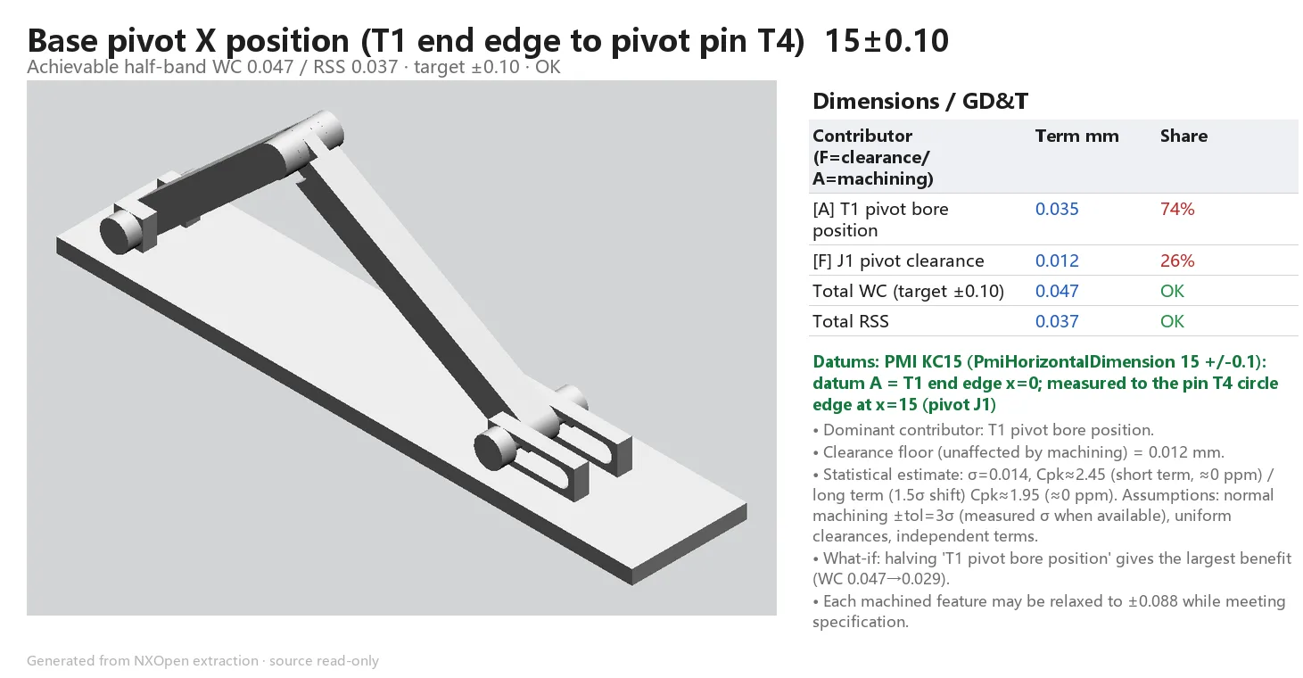
This chart gives the limits of one fit. In an assembly that clearance is one term in a chain, next to the machining terms of the parts around it. On the SuperNX demo part, a planar linkage on a base plate, the base pivot X position (key characteristic KC15, spec 15 ±0.10 mm) has two contributors: the pivot bore position at IT10, ±0.035 mm, and the pivot clearance at Ø6 H7/g6, ±0.012 mm. H7/g6 at Ø6 is 0.004 to 0.024 mm of diametral clearance (H7 is +0/+0.012 mm, g6 is −0.004/−0.012 mm), so the pin can float up to 0.024 / 2 = ±0.012 mm about the bore centre.
Worst case is ±0.047 mm and RSS is ±0.037 mm against the ±0.10 mm spec, so KC15 passes. The bore position is 74% of the worst case and the clearance 26%; halving the bore-position term gives the largest benefit (worst case 0.047 to 0.029 mm), and each machined feature could be relaxed to ±0.088 mm and still meet spec. SuperNX builds these chains for every key characteristic from the NX model.
See the full demo result (no sign-up)
FAQ
What is the H7 tolerance?
H7 is an ISO 286 hole tolerance class: the lower deviation is zero and the upper deviation equals the IT7 tolerance width, which depends on size. For a 25 mm hole IT7 is 21 µm, so H7 means 25.000 to 25.021 mm.
What is the difference between H7 and h6?
The capital letter H is a hole, the lowercase h is a shaft. H7 starts at the nominal size and grows by IT7; h6 ends at the nominal size and shrinks by IT6. At 25 mm H7 is 0 / +21 µm and h6 is 0 / −13 µm, so H7/h6 always leaves between 0 and 34 µm of clearance: a locating fit.
How do I read an H7 tolerance chart?
Find the row whose size range contains your nominal diameter (over the lower value, up to and including the upper), then read the upper and lower deviation in micrometres. Add them to the nominal size to get the limits. Sizes exactly on a boundary belong to the smaller band, so 30 mm uses 18 – 30.
Which shaft goes with an H7 hole?
g6 for a sliding fit, h6 for close locating with clearance, k6 for a transition fit (accurate location, light press) and p6 (or r6 and s6) for a press fit. Use the fit calculator to see the clearance or interference for your size.
Are these values from ISO 286?
Yes. They come from the published ISO 286-1 / ISO 286-2 tables for sizes up to 500 mm, the same data behind the free fit calculator. They are reference values: verify against the current standard before releasing production drawings.